Standardized benchmarks for Computer Vision provide very powerful tools for the development of new improved techniques in the field. Currently frame-free event-driven vision still lacks datasets to assess the accuracy of their methods. This dataset provides both frame-free event data and classic image, motion and depth data to assess different event-based methods and compare them to frame-based conventional Computer Vision. We hope that this will help researchers understand the potential of the new technology of event-based vision.
Event-based sensors and frame-based cameras record very different kinds of data streams. Frame-free sensors collect events that are triggered due to changes in the luminance while conventional sensors collect the luminance of the scene. If we want to compare methods for heterogeneous sensors, we will need conventional sensors and frame-free sensors collecting events from the same scene. To do so we used the DAVIS sensor [1] that collects asynchronous events and synchronous frames.
The mechanism to create the dataset for a frame-free sensor consists in collecting events from the frame-free sensor and additional data from cameras, RGB-D sensors (RGB images plus Depth), inertial sensors, or motion capture systems:
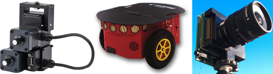
The DAVIS240b sensor (right in the image) is mounted on a stereo rig together with a Microsoft Kinect Sensor that provides the RGB image and the depth map of the scene. The stereo rig is mounted on a Pan Tilt Unit (PTU-46-17P70T by FLIR Motion Control Systems, left in the image). Finally, the Pan Tilt Unit is on-board a Pioneer 3DX Mobile Robot (center in the image). The PTU controls the pan and tilt angles and angular velocities, while the Pioneer 3DX Mobile Robot is in control of the direction of translation and the speed. There are ROS (Robot Operating System) packages available for the PTU and the Pioneer 3DX mobile robot. Our dataset provides the following:
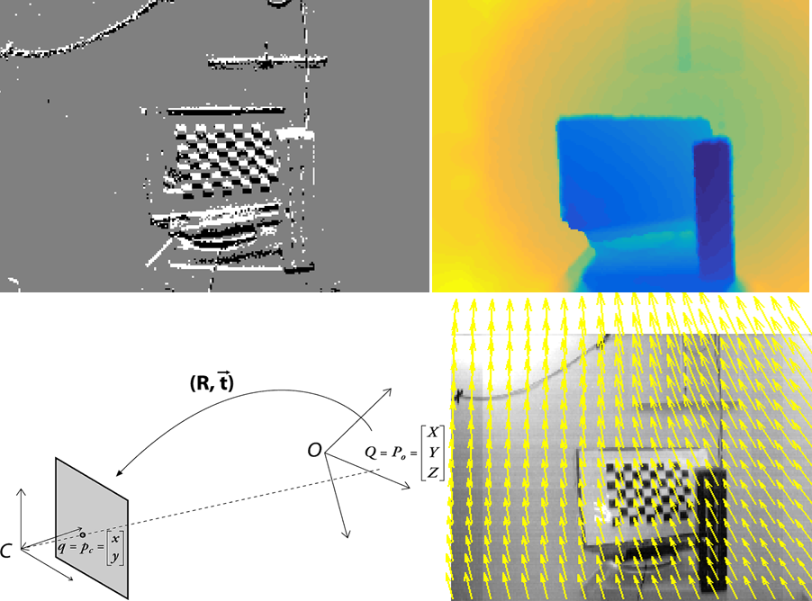
The RGB-D sensor provides the depth of the scene. The RGB data and the Depth in the Kinect sensor are captured by two separate sensors. To obtain the depth rectified with respect to the RGB we use the Kinect SDK. In order to use it in the DAVIS coordinate system, a registration of the depth of the RGB-D sensor is required.
To begin with, we calibrate and extract intrinsic and extrinsic parameters from both DAVIS APS frames and Kinect RGB images. Next, we perform a stereo calibration between the RGB-D sensor and the DAVIS. In other words, the stereo calibration gives us the rotation and translation of the DAVIS with respect to the Kinect.
First, the depth is undistorted using the camera parameters already computed. Next, the 2D coordinates in the image plane are projected into the 3D world coordinates (since the depth is known). The 3D point cloud is then transformed using the rotation and translation computed from the stereo calibration. Last, the new 3D point cloud is projected back into the 2D plane. Now, the new depth registered for the DAVIS coordinate system can be obtained.
The goal is to obtain estimates of the translation and rotation of the camera for a given rotation combination of the pan and tilt of the PTU. The calibration is based on the approach in Appendix D in [3].
The procedure captures images for different combinations of the Pan-Tilt unit , which are used to calibrate the camera with respect to a baseline position (pan=0, tilt=0). This gives us the position of the camera coordinate system (rotation and translation) with respect to the baseline. Then, the DAVIS sensor is calibrated with respect to the center of the PTU unit, using all the rotations and translations computed previously for the different combinations. This is done formulating a minimization problem that is solved searching for the translation, and then solving for rotation. Then the rotation of the DAVIS sensor coordinate system is computed, using simple averaging. The details can be found in the paper. The code is also available in the Section Resources.
The image motion flow field is the projection of the velocities of 3D scene points onto the image plane. The 3D velocities relate the 3D points \textbf{P} = (X, Y, Z) and their instantaneous motion \textbf{\.{P}} = -\textbf{t} - \textbf{\textit{w}} \times \textbf{P}, using Longuet-Higgins and Prazdny's model [4]. The 3D instantaneous motion \textbf{\.{P}} is then obtained as the sum of the translational velocity \textbf{t}=(t_{1}, t_{2}, t_{3}) and the rotational velocity \textbf{\textit{w}}=(\textit{w}_{1}, \textit{w}_{2}, \textit{w}_{3}). Now, the equation that relates the velocity in the image plane (\textbf{u}, \textbf{v}) with the 2D coordinates in the image plane (x,y), the 3D translation and 3D rotation, and the depth \textbf{Z} is
@article{barranco_dataset_2015,
	author = {Barranco, F. and Fermuller, C. and Aloimonos, Y. and Delbruck, T.},
	title = "A Dataset for Visual Navigation with Neuromorphic Methods",
	journal = "Frontiers in Neuroscience",
	year = "2015",
	month= "Nov.",
}
| Sequence 0001 | Data | Ground-Truth | Sequence 0002 | Data | Ground-Truth | Sequence 0003 | Data | Ground-Truth |
| Sequence 0004 | Data | Ground-Truth | Sequence 0005 | Data | Ground-Truth | Sequence 0006 | Data | Ground-Truth |
| Sequence 0007 | Data | Ground-Truth | Sequence 0008 | Data | Ground-Truth | Sequence 0009 | Data | Ground-Truth |
| Sequence 0010 | Data | Ground-Truth | Sequence 0011 | Data | Ground-Truth | Sequence 0012 | Data | Ground-Truth |
| Sequence 0013 | Data | Ground-Truth | Sequence 0014 | Data | Ground-Truth | Sequence 0015 | Data | Ground-Truth |
| Sequence 0016 | Data | Ground-Truth | Sequence 0017 | Data | Ground-Truth | Sequence 0018 | Data | Ground-Truth |
| Sequence 0019 | Data | Ground-Truth | Sequence 0020 | Data | Ground-Truth | Sequence 0021 | Data | Ground-Truth |
| Sequence 0022 | Data | Ground-Truth | Sequence 0023 | Data | Ground-Truth | Sequence 0024 | Data | Ground-Truth |
| Sequence 0025 | Data | Ground-Truth | Sequence 0026 | Data | Ground-Truth | Sequence 0027 | Data | Ground-Truth |
| Sequence 0028 | Data | Ground-Truth | Sequence 0029 | Data | Ground-Truth | Sequence 0030 | Data | Ground-Truth |
| Sequence 0031 | Data | Ground-Truth | Sequence 0032 | Data | Ground-Truth | Sequence 0033 | Data | Ground-Truth |
| Sequence 0034 | Data | Ground-Truth | Sequence 0035 | Data | Ground-Truth | Sequence 0036 | Data | Ground-Truth |
| Sequence 0037 | Data | Ground-Truth | Sequence 0038 | Data | Ground-Truth | Sequence 0039 | Data | Ground-Truth |
| Sequence 0040 | Data | Ground-Truth | Sequence 0041 | Data | Ground-Truth | |||
| Artificial sequences | Data | Ground-Truth |
Questions? Please contact fbarranco "at" ugr dot es